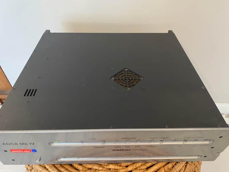
EMM LABS ADC8 Mk IV
EMM LABS
ADC8 Mk IV
- Condition
- Mint
- Type
- DAC
Ships to you
Posted with tracking, and shipping is included — the price you see is the price you pay. This one takes up to seven days to go out, and you'll get the tracking the moment it does.
Description
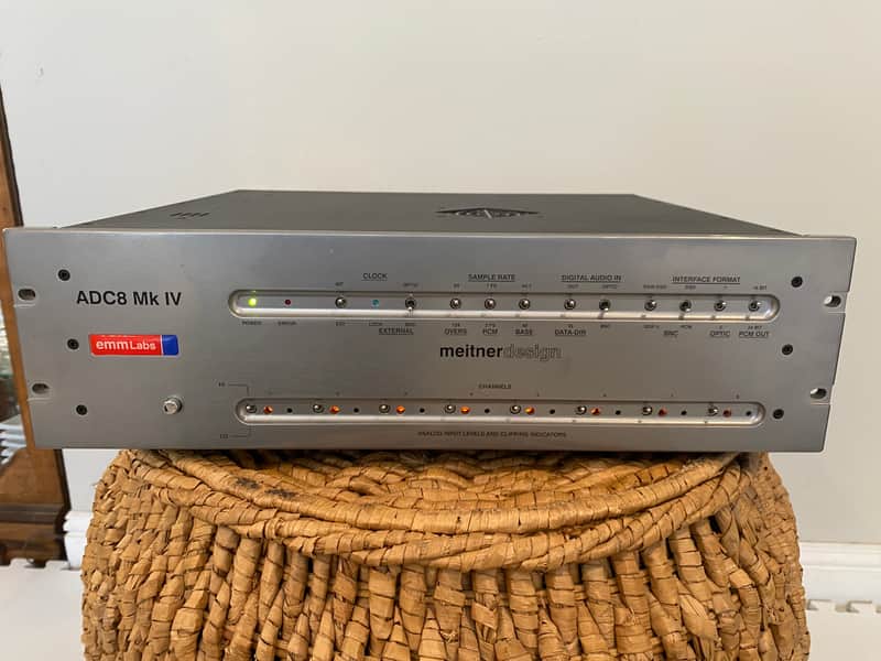
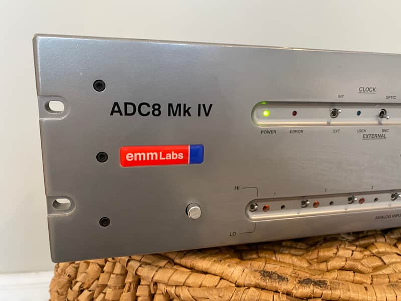
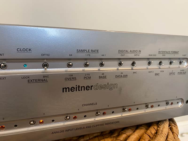
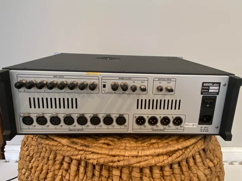
The features and specs are as follows: • 8-channel conversions: • from analogue to PCM (16/24 bits selectable and 44.1kHz - 96kHz) • from analogue to DSD • from DSD to PCM (44.1kHz - 16/24 bits selectable) • from DSD on optical to DSD on BNC connectors • from DSD on BNC to DSD on optical connectors • Supported output formats: • AES/EBU (4 connectors) for PCM • “RAW DSD” (legacy format for DSD on BNC connectors) • SDIF-3 for DSD on BNC connectors • SDIF-2 for PCM on BNC connectors • ST Fiber optic for DSD • Supported input formats: • Balanced analogue 8dbu - 32dbu (pin 2 hot), switchable ranges 8dbu-20dbu / 20dbu - 32 DBU. • “RAW DSD” (legacy format for DSD on BNC connectors) • SDIF-3 for DSD on BNC connectors • ST Fiber optic for DSD • Power supply • power factor corrected • auto-ranging 85V - 240V, 50/60Hz • power consumption: 60W • Analog input impedances • in HI gain position: 30kΩ balanced, 15kΩ unbalanced • in LO gain position: 68kΩ balanced, 34kΩ unbalanced Clock Section INT /EXT: Selects an internal or external clock source. LOCK LED is lit when the A/D converter is locked to an external clock. OPTIC / BNC: Selects the external clock between optical and BNC formats. Sample Rate Section 64 / 128: Selects the oversampling ratio. 128 position does not allow 2FS PCM generation (error light on). 1FS / 2FS: Selects the sample rate for PCM data. FS is the base frequency (see 44.1 / 48 switch). 2FS position will mute outputs when the oversampling ratio is set to 128. 44.1 / 48: Selects the base frequency (only 44.1kHz is allowed for DSD outputs and inputs). Digital Audio Input Section OUT / IN: OUT position selects conversion from analogue to digital. IN position selects conversion from digital to digital. OPTIC / BNC: If the DATA DIR switch is set to IN, this selects data input between optical or BNC connectors (data format is selected in Interface Format Section). Interface Format Section RAW / SDIF-3: When DSD is on BNC the user has the choice between RAW and SDIF-3 formats. DSD / PCM: This switch selects DSD or PCM format on the BNC connectors (in both directions). OPTIC1 / OPTIC2: Selects format 1or 2 for both input and output (currently not implemented - only 1 format). 16 / 24 BITS: The wordlength of the PCM outputs can be selected between 16 and 24 bits. The 16-bit position uses noise shaping to convert original format of 24 bits to 16 bits. Error Indicator is lit for illegal switch positions (audio outputs are muted) Analog Input Level LO / HI: The LO position allows the user to set levels between +20dbu and +32dbu. The HI position allows the user to set the levels between +8dbu and +20dbu. Clipping indicators The clipping LED’s come on when the level on the PCM outputs reach 0dbFS. This level corresponds to 0dbSACD on all DSD outputs. However, the levels on the DSD outputs are allowed to go up to +3dbSACD
Condition notes
Excellent
Seller
Westlake Village, CA
★ 5.00
Description
The features and specs are as follows: • 8-channel conversions: • from analogue to PCM (16/24 bits selectable and 44.1kHz - 96kHz) • from analogue to DSD • from DSD to PCM (44.1kHz - 16/24 bits selectable) • from DSD on optical to DSD on BNC connectors • from DSD on BNC to DSD on optical connectors • Supported output formats: • AES/EBU (4 connectors) for PCM • “RAW DSD” (legacy format for DSD on BNC connectors) • SDIF-3 for DSD on BNC connectors • SDIF-2 for PCM on BNC connectors • ST Fiber optic for DSD • Supported input formats: • Balanced analogue 8dbu - 32dbu (pin 2 hot), switchable ranges 8dbu-20dbu / 20dbu - 32 DBU. • “RAW DSD” (legacy format for DSD on BNC connectors) • SDIF-3 for DSD on BNC connectors • ST Fiber optic for DSD • Power supply • power factor corrected • auto-ranging 85V - 240V, 50/60Hz • power consumption: 60W • Analog input impedances • in HI gain position: 30kΩ balanced, 15kΩ unbalanced • in LO gain position: 68kΩ balanced, 34kΩ unbalanced Clock Section INT /EXT: Selects an internal or external clock source. LOCK LED is lit when the A/D converter is locked to an external clock. OPTIC / BNC: Selects the external clock between optical and BNC formats. Sample Rate Section 64 / 128: Selects the oversampling ratio. 128 position does not allow 2FS PCM generation (error light on). 1FS / 2FS: Selects the sample rate for PCM data. FS is the base frequency (see 44.1 / 48 switch). 2FS position will mute outputs when the oversampling ratio is set to 128. 44.1 / 48: Selects the base frequency (only 44.1kHz is allowed for DSD outputs and inputs). Digital Audio Input Section OUT / IN: OUT position selects conversion from analogue to digital. IN position selects conversion from digital to digital. OPTIC / BNC: If the DATA DIR switch is set to IN, this selects data input between optical or BNC connectors (data format is selected in Interface Format Section). Interface Format Section RAW / SDIF-3: When DSD is on BNC the user has the choice between RAW and SDIF-3 formats. DSD / PCM: This switch selects DSD or PCM format on the BNC connectors (in both directions). OPTIC1 / OPTIC2: Selects format 1or 2 for both input and output (currently not implemented - only 1 format). 16 / 24 BITS: The wordlength of the PCM outputs can be selected between 16 and 24 bits. The 16-bit position uses noise shaping to convert original format of 24 bits to 16 bits. Error Indicator is lit for illegal switch positions (audio outputs are muted) Analog Input Level LO / HI: The LO position allows the user to set levels between +20dbu and +32dbu. The HI position allows the user to set the levels between +8dbu and +20dbu. Clipping indicators The clipping LED’s come on when the level on the PCM outputs reach 0dbFS. This level corresponds to 0dbSACD on all DSD outputs. However, the levels on the DSD outputs are allowed to go up to +3dbSACD
Condition notes
Excellent
SPKRS holds your payment until you confirm you have the item.